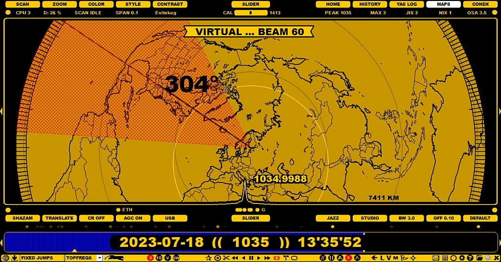
If you want to evaluate antenna beams and directions without any antenna definitions, you can use the ANTENNAS display for "virtual" antenna tests.
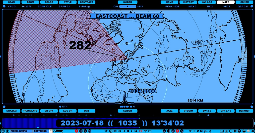
If you have defined your antennas in the SETTINGS > KIT > ANTENNAS window, the ANTENNAS display will show them accordingly. You can select an antenna for example by clicking it on the map, or by pressing the "A" key repeatedly until the desired antenna becomes red.
"A for ANTENNAS" works only if you have defined ANTENNAS and only in the LIVE mode, otherwise the keyboard key "A" will always trigger the COMPARE tool (see COMPARE for more details).
The selected antenna becomes your "current antenna", and the name defined for it will be added as a suffix to the file name of your recordings.
In addition, JAGUAR can also make a physical antenna change if you use either Devantech or Velleman relay boards (or a third-party antenna switcher which can be invoked from JAGUAR).
The ANTENNAS map can be shown by pressing the "A" key (in the LIVE mode only and only if you have defined SETTINGS > KIT > ANTENNAS), or by clicking TOOLBAR > M > ANTENNAS.
The ANTENNAS display has the following characteristics:
When the mouse cursor is over the red antenna beam, you can increase/decrease the beam with in steps of 5 degrees using the mouse wheel or left/right arrow keys.
In addition, the distance (km) from your QTH to the position pointed by the mouse pointer is shown on the lower right corner of the display.
You can define your JAGUAR antenna setup by opening the SETTINGS > KIT > ANTENNAS window and making a definition for each antenna. The defined antennas will be shown on the ANTENNAS map. Antenna switches are also supported; JAGUAR has a built-in support for the Velleman and Devantech antenna relay boards. These boards can also be used to switch the preamp on/off. If you have the Velleman/Devantech relay boards, their drivers must be installed first, and the COMPORT parameter (given by Windows OS, for example COM5) must be defined in the last row.
Let us assume that you have four beverage antennas, beamed at 293, 320, 35 and 80 degrees (with an estimated beam width of 60 degrees) and a preamp is also used. In the following example, the Velleman relay board is used: the slots 1-4 have the antennas and the slot 8 has the preamp. Each line is entered by clicking the "CHANGE" button, adding one antenna definition into the corresponding text box and then clicking "SAVE" for the added antenna).
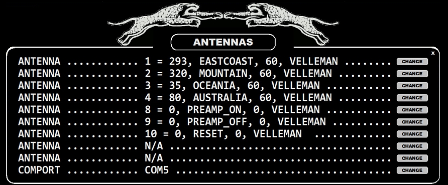
Each ANTENNAS line consists of the antenna number and three parameters: direction, name, beam width (or scan target, see below). The fourth parameter is optional: it can be either "VELLEMAN" or "DEVANTECH" (if you use either of these antenna relay boards for the antenna switches) or it can be any third-party antenna switch that can be invoked from the command line - in that case the full path to that CMD/BAT file must be given as the fourth parameter.
The antennas can now be switched as follows:
The third parameter (beam width) can be replaced by the default scan target of the antenna (MW9 or MW10). If MW9 or MW10 is used (instead of the beam width), the system will change the LIVESCAN target automatically when the antenna is switched (see GUIDE > LIVESCAN for more details).
This is a handy feature when LIVESCAN is used: for example, a scheduled SET ANTENNA function will change both the antenna direction and the LIVESCAN scan target at the same time. If MW9/MW10 is defined for any antenna, the default width of 60 degrees is used as the beam width for that antenna on the ANTENNAS display.